How do you design a drivetrain that nobody has built yet? You start on a computer, with a virtual turbine. This article explains wind turbine loads, the simulations behind them and the design loop that links them. It also shows how LIGHTWIND has used that loop so far.
Start with a virtual turbine
An aeroelastic model is a computer simulation of a whole wind turbine. It combines two things. First, how the wind acts on the blades. Second, how the blades, tower and drivetrain bend and vibrate in response.
LIGHTWIND started from the IEA 15 MW reference turbine, an openly published design that researchers use as a common starting point. Its full model is also available on GitHub. New to the topic? Our explainer on the wind turbine drivetrain covers what this part of the turbine does.
Put the drivetrain inside the model
The drivetrain is modelled as a set of connected bodies. Each one has its own mass and stiffness. Engineers then plug this drivetrain model into the turbine simulation.
The first LIGHTWIND version used today’s established modelling methods. As a result, the team expected its accuracy to be limited. Still, it was good enough to produce a first set of loads.
What wind turbine loads are
Loads are the forces a component has to withstand. They come from steady wind, sudden gusts, the weight of parts as they turn and the twisting of the rotor. Design standards such as IEC 61400-1 ask engineers to check many situations. These include normal operation, extreme gusts, start-up and shutdown, and faults.
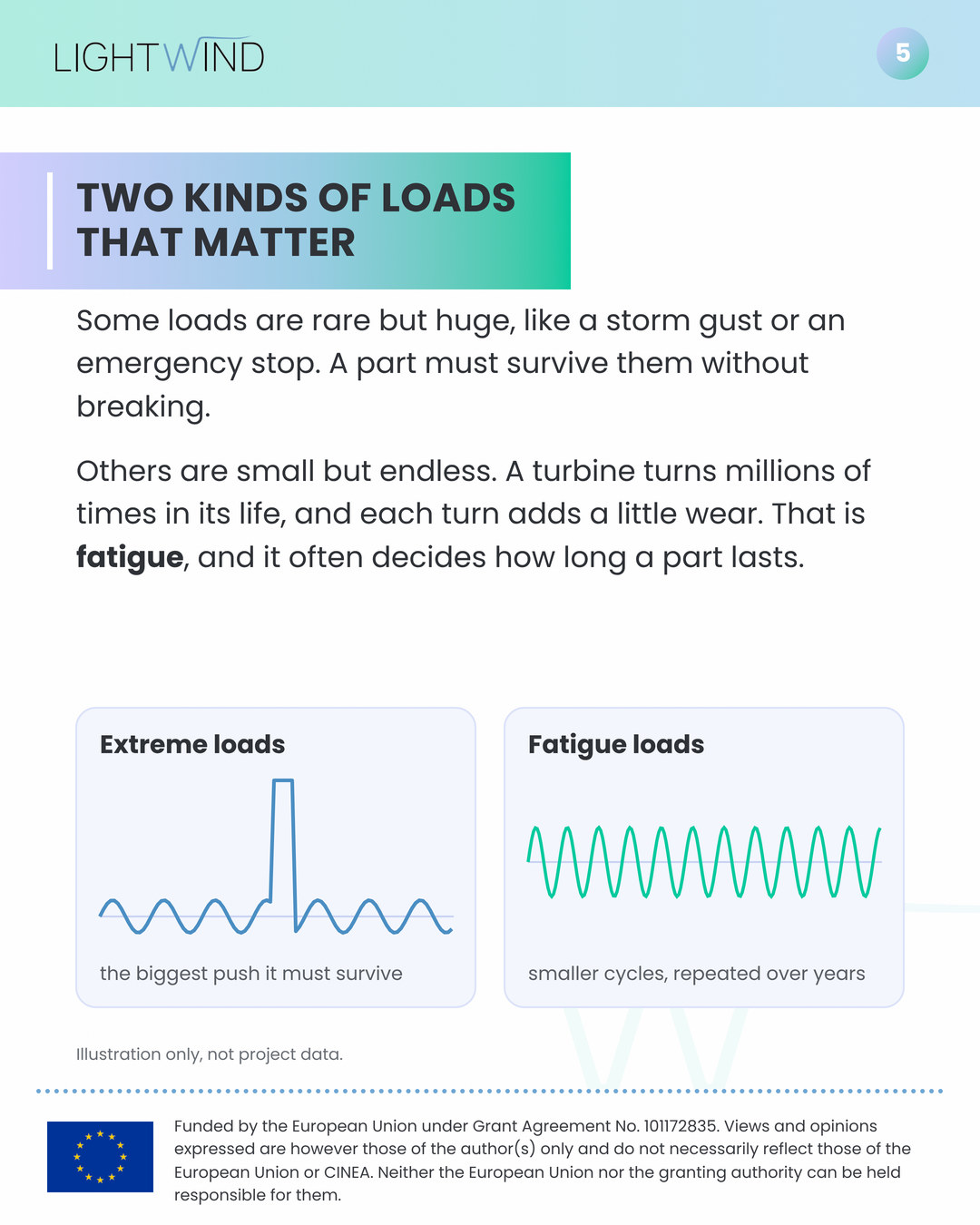
Engineers usually think about two kinds of loads. Extreme loads are rare but huge, like a storm gust or an emergency stop. A part must survive them without breaking. Fatigue loads, on the other hand, are small but endless. A turbine turns millions of times in its life, and each turn adds a little wear. In practice, fatigue often decides how long a part lasts.
The design loop
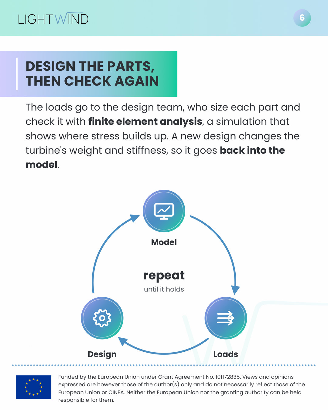
Next, the loads go to the design team. They size each part and check it with finite element analysis, a simulation that shows where stress builds up. However, a new design changes the turbine’s weight and stiffness. That changes the loads too. So the updated design goes back into the model, and the loop starts again.
In LIGHTWIND’s first round, our partner TNO built the turbine model with an early version of the LIGHTWIND drivetrain inside. Model and design then went round the loop three times, until the team was confident enough to move on.
From simulation to the lab
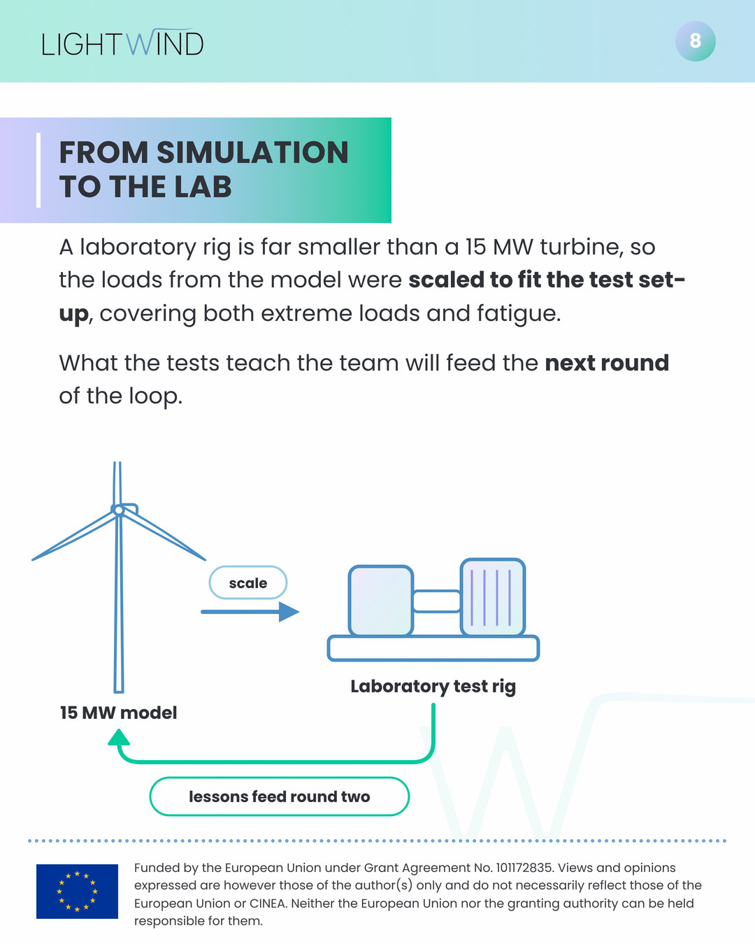
A laboratory rig is far smaller than a 15 MW turbine. For that reason, the loads from the model were scaled to fit the test set-up, covering both extreme loads and fatigue. You can read the project’s public reports on design methodologies and validation plans on our results page.
What the tests teach the team will feed the next round of the loop.
What comes next
The next round brings an updated turbine model and an updated set of loads, built with what the project learns from testing. The updated model is expected to describe the real drivetrain more reliably. Later, it will also help adapt the design to a floating foundation.
Want to explore further? Read how modular drivetrains could change maintenance at sea, or see how the project looks at underwater noise from offshore wind. You can also find LIGHTWIND on CORDIS, the EU’s database of funded research, and follow us on LinkedIn and Bluesky.
Further reading
Gaertner, E. et al. (2020). Definition of the IEA 15-Megawatt Offshore Reference Wind Turbine. National Renewable Energy Laboratory, IEA Wind Task 37.
IEA Wind Task 37. IEA 15 MW reference wind turbine model files. GitHub.
International Electrotechnical Commission. IEC 61400-1:2019, Wind energy generation systems, Part 1: Design requirements.